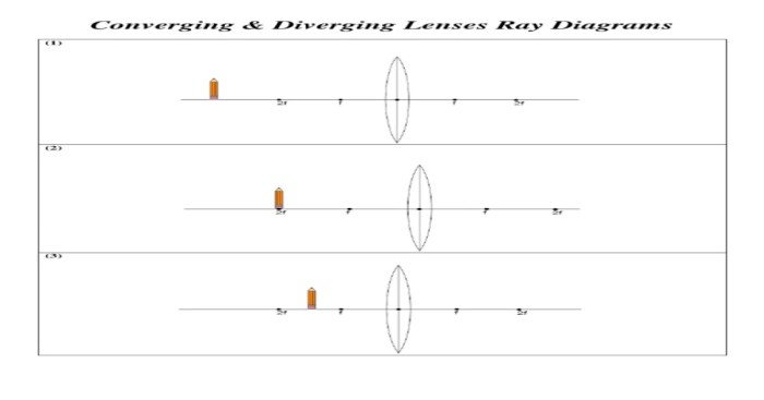
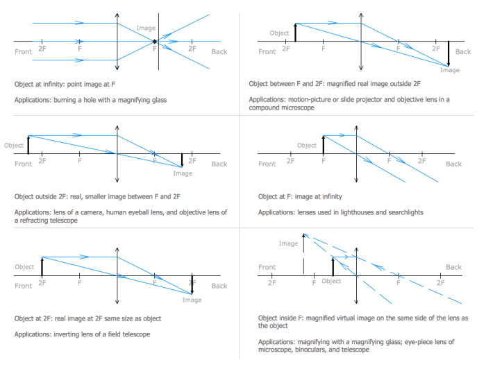
Ray diagrams for converging lenses worksheet answers provide a comprehensive guide to understanding the principles and applications of ray diagrams in optics. This detailed resource offers a step-by-step approach to constructing ray diagrams, exploring image formation, and delving into the practical uses of ray diagrams in various fields.
By understanding the behavior of light rays passing through converging lenses, individuals can gain valuable insights into the fundamentals of optics and its real-world applications.
Ray Diagrams for Converging Lenses: Introduction
Ray diagrams are graphical representations used to trace the path of light rays through optical systems. They are a fundamental tool in optics, enabling the analysis and design of lenses, mirrors, and other optical components.
Converging lenses are optical elements that cause light rays to converge (meet) at a point. They have a positive focal length and are thicker in the middle than at the edges. Understanding the properties of converging lenses and how they affect light rays is crucial for understanding the formation of images and the design of optical systems.
Constructing Ray Diagrams for Converging Lenses

To construct a ray diagram for a converging lens, follow these steps:
- Draw the principal axis of the lens as a horizontal line.
- Mark the optical center (O) of the lens on the principal axis.
- Draw the focal points (F) on the principal axis, one on each side of the lens, at a distance equal to the focal length (f) from the optical center.
- Draw three rays from the object point (P):
- Ray 1: Parallel to the principal axis, passing through the center of the lens (O).
- Ray 2: Passing through the center of curvature (C) of the lens.
- Ray 3: Passing through the focal point (F) on one side of the lens.
- Trace the refracted rays after passing through the lens:
- Ray 1: Refracted through the optical center (O) and continues parallel to the principal axis.
- Ray 2: Refracted through the center of curvature (C) and passes through the focal point (F) on the other side of the lens.
- Ray 3: Refracted through the focal point (F) on one side of the lens and passes through the focal point (F) on the other side of the lens.
- The point where the refracted rays intersect is the image point (P’).
Image Formation by Converging Lenses

Converging lenses form real and inverted images when the object is placed beyond the focal point. The image is formed on the opposite side of the lens from the object.
The relationship between object distance (u), image distance (v), and focal length (f) is given by the thin lens equation:
1/u + 1/v = 1/f
The magnification (M) of the image is given by:
M = v/u =
h’/h
where h’ is the image height and h is the object height.
Applications of Ray Diagrams for Converging Lenses: Ray Diagrams For Converging Lenses Worksheet Answers

Ray diagrams for converging lenses are used in various practical applications, including:
- Photography: Designing lenses for cameras to control the image size, field of view, and depth of field.
- Microscopy: Designing lenses for microscopes to magnify small objects and create clear images.
- Optical instruments: Designing lenses for telescopes, binoculars, and other optical instruments to enhance image quality and functionality.
- Optical system design: Analyzing and optimizing the performance of optical systems, such as lens combinations and imaging systems.
Interactive Ray Diagram Simulation

Interactive ray diagram simulations allow users to explore the behavior of light rays through converging lenses and visualize the formation of images.
These simulations typically provide:
- Adjustable object and lens parameters (e.g., object distance, focal length).
- Real-time tracing of light rays through the lens.
- Measurement tools to determine image distance, magnification, and other parameters.
By manipulating the simulation parameters, users can gain a deeper understanding of the principles of ray diagrams and image formation.
FAQ Guide
What is the purpose of a ray diagram?
A ray diagram is a graphical representation used to trace the path of light rays through an optical system, helping visualize the formation of images.
How are ray diagrams constructed for converging lenses?
Ray diagrams for converging lenses are constructed by drawing rays from an object point through the lens and tracing their paths to the image point.
What is the relationship between object distance, image distance, and focal length for converging lenses?
The relationship is given by the thin lens equation: 1/f = 1/do + 1/di, where f is the focal length, do is the object distance, and di is the image distance.